Page
Perform Start-Up and Shut Down Procedures
Completion requirements
View
Starting up and Shutting Down Pumps
Proper starting and shutting down of pumps will ensure that the pump will operate optimally for a long time.
It is very important that the delivery valve must be closed before the pump is started or shut down. If the delivery valve is open during start-up, the pump will need more energy to start, resulting in a bigger electricity bill. If the pump is shut down with an open valve, a water hammer can occur, which can damage the internal parts of the pump. Note that some pump installations are equipped with automated hydraulic valves. These valves open and close automatically when the pump is switched on and off.
Starting Up
- Perform the pre-start-up inspection.
- Check that the pump is properly primed
- Close the delivery valve.
- Start the pump by pushing the start button and remain at the panel until the pump runs smoothly (10-20 seconds). If any unusual noise or vibration occurs, immediately press the stop button.
- If the pump runs normally, open the delivery valve slowly.
Shutting Down
- Close the delivery valve slowly, preventing water hammer.
- As soon as the valve is closed, switch off the pump.
Note that just before shutting down the pump is an ideal time to take pressure readings on the filter bank and to back-flush the filters.
Motor and Pump Working Characteristics
Most pump installations are equipped with the following gauges:
- The amp meter is located on the electrical panel and measures the current that is used.
- The voltmeter is located on the electrical panel and gives a reading of the voltage, e.g. 400V.
- The pressure gauge is located on the delivery pipe and gives a reading of the pressure in kPa or Bar.
- The flow meter is installed on the delivery pipe and measures the flow in cubic meters (m3). Mechanical flow meters have a dial gauge on the meter, while electronic flow meters have a digital readout in a special panel.
- Although all pump stations will not necessarily have volt and flow meters, they should at least be equipped with an amp meter and pressure gauge.
The normal readings, or norms, differ from pump to pump. The supervisor or manager should give the norms for amps, volts, pressure and flow. Actual readings are compared with the norms to establish whether the pump and motor are running optimally and to assist with determining the pump and motor characteristics.
Opening and Closing Pressure Control Valves
Pressure control valves are hydraulic valves fitted with a pilot valve and are used to regulate pressure and flow. The pilot valve is a device that regulates the pressure inside the hydraulic valves.
These valves are controlled by a 3-way valve. The 3-way valve is marked Open, Close and Auto. To open the pressure, simply turn the dial to open and to close the valve, turn the dial to Close. To regulate the pressure, or for other automated functions, turn the dial to Auto. Keep in mind that turning the dial to open could burst a pipe because of high pressure. The pilot should be adjusted by the supervisor or manager. Some valves are fitted with pressure points. See section 6 of this chapter for more information on the use of these pressure points.
Possible Problems
After a pump is started in the morning, it must be monitored during the day to ensure that it is running smoothly. Always check the perimeter and working characteristics of the pump as described in previous sections. Also pay attention to vibration, noise, leaks, burst pipes, smoke, sparks, fire, etc. Switch off the pump immediately if any of this should occur and report it to the supervisor or manager.
Infield Valves
Hydraulic, gate or butterfly valves are used as infield valves. To open a gate valve, turn the wheel anticlockwise and to close the valve, turn the wheel clockwise.
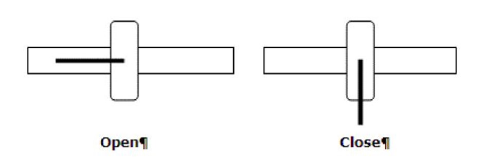
Butterfly Valves
Butterfly valves are equipped with a handle. To open the valve, turn the handle until it is in line with the pipe. To close the valve, turn the handle until it is perpendicular to the pipe. Some butterfly valves are equipped with a wheel and dial. When the wheel is turned, the dial indicates if it is opening or closing.
To set the flow rate for an irrigation block, the pressure needs to be adjusted by opening or closing the valve. To reduce the pressure, close the valve more, and to increase the pressure, open the valve more. All valves underwater pressure must always be opened and closed very slowly to prevent water hammer and the resulting damage. See section 6 for the measuring and regulating of the pressure.
Regulating Infield Valve Pressure
It is very important that the pressure on infield valves is regulated properly and set to the required levels, as the pressure determines the flow rate for the irrigation block. If the pressure is too low, too little water will be delivered to the crops, resulting in water stress that can impact negatively the yield. If the pressure is too high, too much water will be delivered to the crops, which not only will result in water wastage, but also tend to make emitters mist. Misting causes emitters to spray water into the rows between the crops, and not on the root zone.
The correct pressure levels for infield valves are determined and prescribed by the irrigation manager or supervisor. The supervisor or manager will also set the pilot valves that are used on hydraulic valves, and no other person should be allowed to adjust the settings.
Infield valves are located on valve risers or valve clusters. Usually, these risers consist of riser pipes, a valve (hydraulic, gate, butterfly) and either hydromatics or pressure points. A hydromatic is a type of quick coupler that is used for pressure readings.
The hydromatic and pressure points are used to measure the pressure. To measure the pressure using the hydromatic:
- Fit a pressure gauge to a pipette, which fits into the hydromantic, and not to be confused with a pipette that is used in chemistry
- Insert the pipette with the gauge into the hydromatic.
- Make sure the latch on the pipette locks on to the hydromatic.
- The pressure will register on the gauge.
- To release the pipette, push it down, unlock the latch and remove it.
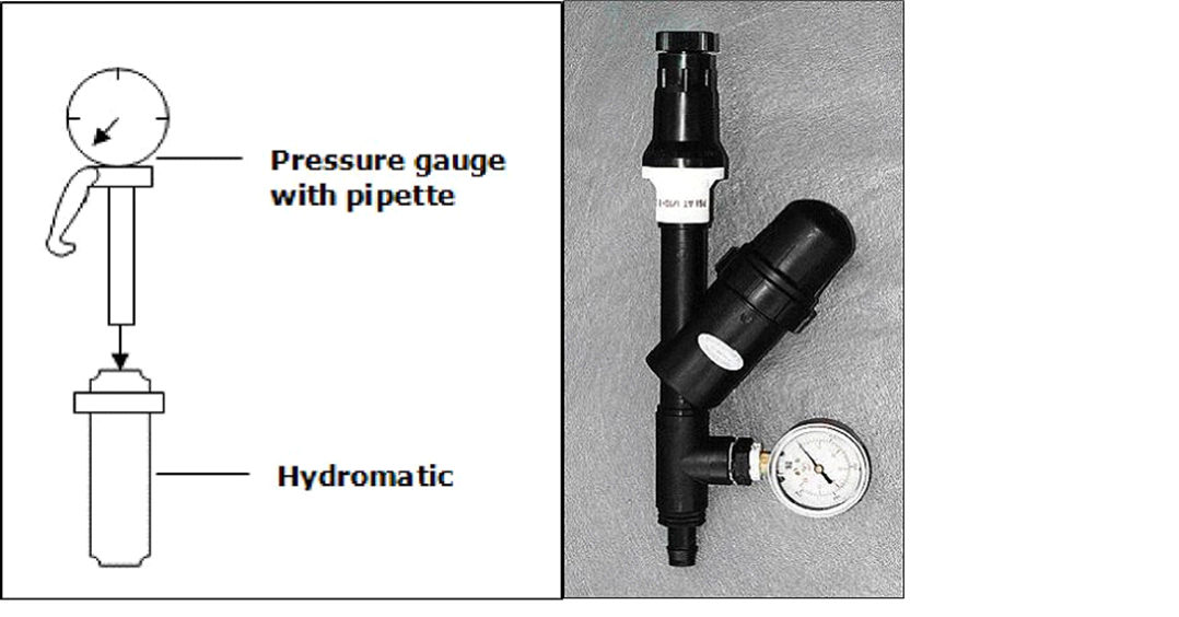
Example of Pipette and Hydromatic
To use the pressure point, the gauge must be fitted with a special needle. To take a pressure reading:
- Insert the needle carefully into the pressure point, as carelessness can damage the silicone nipple inside the pressure point.
- The pressure will register on the gauge.
- Remove the gauge by simply pulling the needle out of the pressure point. Be careful when inserting the needle.
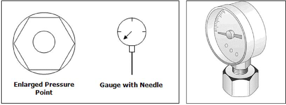
Pressure Point and Gauge with Needle
Where a hydraulic valve is used, the pilot valve is set to regulate the pressure for the irrigation block. It is good practice to take a reading once the valve is open and the pressure is stable, around 10-20 minutes after opening. The norm is 1.8 to 2.3 bar where micro emitters are used but can vary depending on the characteristics of the block. It is however important to note that if the pilot valve is set to for example 2 bar, the reading should not be lower than 1.8 bar or higher than 2.2 bar, which is a 10% tolerance. If the reading is outside this range, it must be reported to the supervisor or manager.
Where a gate or butterfly valve is used, the pressure must be set manually. Insert the gauge into the riser and open the valve slowly. Once the lateral lines in the block have filled with water and the pressure has stabilised, regulate the pressure by turning the wheel, thereby opening and closing the valve. If the required pressure is for example 2 bar, and the reading on the gauge is 1.7 bar, open the valve slowly until the pressure is 2 bar. If the reading is 2.3 bar, close the valve slowly until the reading is 2 bar.
Measuring Infield Filter Pressure
In some irrigation systems, secondary inline filters are fitted. Using the same techniques as for the valves, measure the pressure upstream, being before the filter, downstream, and being after the filter. The difference between the two readings should not be more than 0.5 bar.
If the inline filters are in a bank, i.e. two or more filters are in parallel, the filters can be back-flushed. After back-flushing, take a pressure reading again. If the difference is still greater than 0.5 bar.
- Close the filter inlet valve
- Remove the filter lid
- Remove the elements from the filter
- Clean it with a brush (see the manual for the specific filter)
- Re-insert the elements
- Replace the filter lid
- Open the inlet valve
Take a pressure reading again. If the difference is still larger than 0.5 bar, report this to the supervisor or manager.