Page
3. Shock Loads, Fall Factors, and Anchor Leads
Completion requirements
View
The Terms “Shock Loads, “Fall Factors” and Anchor Loads are Explained
Shock Loading
Shock loading occurs when a load is quickly jerked in any direction or if it is allowed to free-fall before the rigging catches it. Rapid acceleration increases the force put on the rigging system, and if the acceleration is too severe, it can overload the capacity of the system.
When shock loading occurs, although the load itself may be within the load-bearing capabilities, the forces generated by the shock loading can momentarily increase the load beyond the ratings. This can damage certain units and permanently affect performance and durability.
Anchorages to which personal fall arrest equipment is attached shall be capable of supporting at least 5,000 pounds (22.2 kN) per employee attached or shall be designed, installed, and used as part of a complete personal fall arrest system which maintains a safety factor of at least two, under the supervision of an engineer.
Fall Factor
The fall factor is simply the distance fallen, divided by the amount of rope available to absorb that fall. The principle is that the lower the fall factor, the safer the fall.
The fall factor is the ratio between the height of the fall and the length of rope that is available to absorb that fall. The value of the fall factor varies between 0 and 2 and is calculated by dividing the height of the fall by the length of the rope. The height of a fall is measured from the point where a person falls to the point that the fall is stopped.
The lower the value of the fall factor, the fewer impact forces are applied to the body of the person and the ‘safer’ the fall. On the other hand, the higher the value, the greater the impact forces on the body will be and the more likely it is that serious injuries are sustained. Note that the fall factor is a way to indicate the severity of a fall, not an exact way to measure impact forces.
To get a better picture of what the fall factor is and how it’s calculated, we will provide some basic examples below, based on climbing images. As mentioned in the paragraph above, the fall factor is calculated following the equation:
Height of the fall
Fall factor = -----------------------------
Length of the rope
Note that factors like the elasticity of the rope and hitting objects are taken out of the equation.
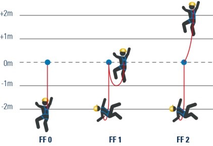
Example 1
The anchor point of the climber is placed overhead and the rope is pulled tight during the climb. In the example, the rope length is 2m. When the climber loses grip and falls, the fall distance is 0 because of the taut rope. This results in the following equation:
0 meters fall height
--------------------------- = Fall factor 0
2 meters of rope
In this case, the impact force on the user’s body is minimal, which is a safe value for the climber. The person would sustain some bruises in most cases.
Example 2
In this example, the total rope length is 2m as well. But now, the person climbs higher up to the same height as the anchor point. If the climber should fall, the distance of that fall will be 2m
2 meters fall height
--------------------------- = Fall factor 1
2 meters of rope
A fall factor of 1 is reached here, which means that impact forces come into play that can possibly injure the climber, like breakage of limbs or a concussion.
Example 3
The highest amount of force that is released on the climber’s body is reached when the climber climbs to 2m above the anchor point with a rope of 2m.
In case of a fall, the climber will fall a total of 4m, resulting in the maximum fall factor:
4 meters fall height
--------------------------- = Fall factor 2
2 meters of rope
The impact forces on the body are dangerously high when a fall factor of 2 is reached and the climber will sustain serious and possibly life-threatening injuries because of it.
In the table below, you find a schematic overview of the fall factors as described above:
Fall Factor and Fall Protection Systems
In practice, the examples given in the previous section aren’t representative of occupational situations where work at height is performed and fall protection is needed. In this section, we will put the examples into practice.
Fall Factor 0
An example with an overhead fall protection system
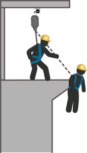
When workers need to work at height and a ceiling or another structural element is located above them, the use of an overhead fall protection system is recommended. Especially in combination with an automatic fall arrest device (also known as a retractable device). This retractable device acts like a seatbelt: it keeps the lanyard taut at all times and will block immediately when a sudden acceleration occurs (a fall).
The image shows that the fall distance is very minimal. Only the extension of the energy absorber will add to the fall height (in case a retractable device has a built-in energy absorber, the rope will not extend). The lanyard will be the length of the distance between the attachment point on the harness and the anchor point, which is a horizontal lifeline in most cases.
If we do a basic calculation with the anchor point 1 meter above the attachment point of the harness, the fall factor would be:
0.75 meters fall height
--------------------------- = Fall factor 0.75
1m of rope
Fall Factor 1
Example with a wall-mounted lifeline system
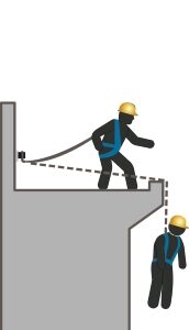
If the anchor point is located at waist height and the attachment point of the lanyard is located at the back of the worker, the fall factor will be around 1.
In the example, an overhead system is not possible, so the anchor point (a horizontal lifeline) is mounted at waist height on a wall.
In this situation, the lanyard is 2m. When a fall occurs, the user will fall approximately 2m as well. The protruding working area will somewhat decrease the fall distance, but the deflection of the lifeline will add to that again.
2 meters fall height
--------------------------- = Fall factor 1
2 meters of rope
The impact forces will be quite high in this situation, that’s why a personal energy absorber (PEA) needs to be used, which decreases the forces and decreases the chance of (serious) injuries caused due to those forces.
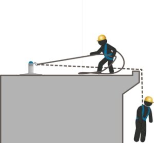
Fall Factor 2
Example with a horizontal lifeline system
Horizontal lifeline systems and other systems where the anchor points are located at foot level are generally installed on roofs. When a user falls, they fall the distance of the attachment point to the height of the anchor point (2 meters) and the distance of the lanyard below the anchor point (2 meters).
In the example, this means a fall distance of approximately 4 meters. When putting this into the equation, we get a fall factor of 2.
4 meters fall height
--------------------------- = Fall factor 2
2 meters of rope
The impact forces that are released on the body will be very high. That’s why a personal energy absorber has to be used in these systems. This will add to the fall height by 0,75m but it will significantly reduce the impact forces and decrease the risk of serious injuries.
The examples given do not entirely cover real-life situations, because elements like rope flexibility, use of an energy absorber, deflection of the wire rope, a distance of the anchor point to the roof edge etc. will have an impact on the impact forces as well. Also, the distance to the next level below the working area is not determined (fall clearance).
Nevertheless, keeping the above in mind will help in choosing the most appropriate configuration for your fall protection system: whenever possible, strive to minimize the fall factor to 0.
Anchor Loads

When eye nuts are used for fall protection they must comply with the relevant testing loads and procedures contained in the various standards.
Persons who select to install and test eye nuts and structural anchors must be competent to perform that work. Suitable training programmes are recognized by the Institute for Work at Height (IWH)
Do other forms of training or registration make a person competent?
The short answer is NO
To be competent in anchor point selection you should have received proper anchor point training which addresses at least the following topics:
- Reaction loads and direction of applied loads
- Test loads as per the standards
- In-service loads
- Resultant forces
- Combined shear and tensile forces and limitations
- Bending moments and bending stress
- Allowable stress in anchor bolts/size/mechanical grade
- Supporting structures/substrates
- Load testing vs pull-out testing
- Minimum anchor size and embedded depth
- Minimum edge distances and anchor spacing
- The training programmes recognized by the IWH cover anchor points for fall prevention and fall arrest for use by one person only
Any requirement or installation of anchors that exceed the criteria of type “A” anchor devices shall only be done after the design of such systems has been undertaken/approved by competent engineering professionals
Cast Eyenuts
All anchor points (also known as “hangers”) need to be pulled up tight against a hard, load-bearing surface such as normal concrete. The plaster covering (aka “rendering”) over a concrete surface is not hard nor is it load bearing. An anchor point fitted up against such plaster will cause the bolt to bend during a fall arrest situation. So, the correct installation requires that all the “soft” materials (plaster and non-load bearing waterproofing) be removed between the contact surface of the eye nuts and the concrete.
Of critical importance is the correct orientation of the eye nuts to ensure that it is not subjected to what is known as “cross-loading” or “lateral loading”. Eye nuts can only take their full rated load in a direction that is in line with the anchor bolt i.e. pure axial loading.
A reduced load can be applied along the perimeter of the ring but only in a direction that is in line with the shape of the ring of the eye nuts. If the eye nuts are positioned so that the ring is in a vertical orientation, then the load on the eye nuts needs to also be in that vertical direction.
The reduction in the safe working load is significant. The allowable load at right-angles (90 degrees) to the direction of the anchor bolt is only half of the safe working load stamped on the eye nuts.
“Cross loading” or “lateral loading” is a situation where the load is not applied radially along the curvature of the ring part of the eye nuts. This load is applied onto the side of the ring and is not permitted by the manufacturers.
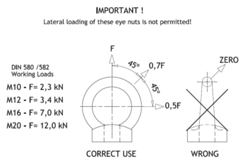
Eye nut loading limitations. Lateral loads are prohibited
The Importance of Load Direction
Once an anchor is chemically set into the concrete structure it can no longer be turned and when the eye nuts are then tightened onto the threads of the anchor, the chances of the orientation of the eye nuts lining up in exactly the right direction of the applied load is almost nil.
When you tighten the eye nuts, the ring must end up exactly in that direction! What are the chances of that happening? And if you then unwind the eye nut to get the orientation right, then the nut is loose and does not press tightly against the concrete. The anchor bolt can now bend under fall arrest loads and the nut might work itself completely loose with fatal results in a fall arrest or fall prevention situation.
Fitting normal-sized flat washers between the eye nuts and the concrete structure are also not the best solution as the outer diameter of standard washers is smaller than the diameter of the base of the eye nuts thus leaving the anchor bolt unsupported and exposed to bending forces.
The vast majority of existing eye nuts installations use M12 anchor bolts. Look at the working loads for the top-of-the-range, high-quality DIN standard eye nuts as illustrated in the image above. An M12 DIN 582 eye nuts are limited to 340kG axial load. All fall arrest anchor devices should have a minimum working load capacity of 600kg so M12 eye nuts cannot be safely specified for fall arrest use.
Important Note:
The use of anchors set into brick walls, precast concrete block walls or materials other than in-situ cast concrete is beyond to scope of competency envisaged in the above-mentioned course and must be avoided. South African face bricks are not cast as solid units and have holes through them which make them unsuitable as structural substrates (base materials) for fall arrest anchors.
In all cases where the base material is anything other than grade C20/25 in-situ cast concrete, you should refer the matter to a professional engineer that has experience in this field.
Single point anchor fall protection design considerations non-engineered single point anchors must be rated at 5,000 kg (2.3 ton) for one user or 4.6 ton for two users. Engineered systems must be designed for 2 x the applied load in the event of a fall by a qualified person.