Page
Irrigation Design
Completion requirements
View
The foundation of a high-quality irrigation system is a good irrigation design plan. The irrigation system should be designed by a qualified irrigation designer. The SA Irrigation Institute (SABI) has a specific designer membership which is attainable by passing an exam. Below is an example of an irrigation design plan for three adjacent blocks of a micro sprayer irrigation system for a fruit orchard.
Design Plan

Orientation
When reading an irrigation design plan, the first step is to get the orientation right. The plan must be turned so that landmarks on the plan agree with the actual landmarks, such as dams, canals, koppies (hillock), or any other distinguishable features that is shown on the map. Familiarise yourself with the block and pipe layout on the plan and compare it with the actual block and pipe layout (if it is an existing system).
Symbols
On an irrigation design plan symbols or different colours are used to depict the various pipes, valves and other features. Usually, a key is provided with the symbols and their meaning. In the table below, the symbols and keys that are shown on the irrigation design plan above are explained further.

Pipe Notations
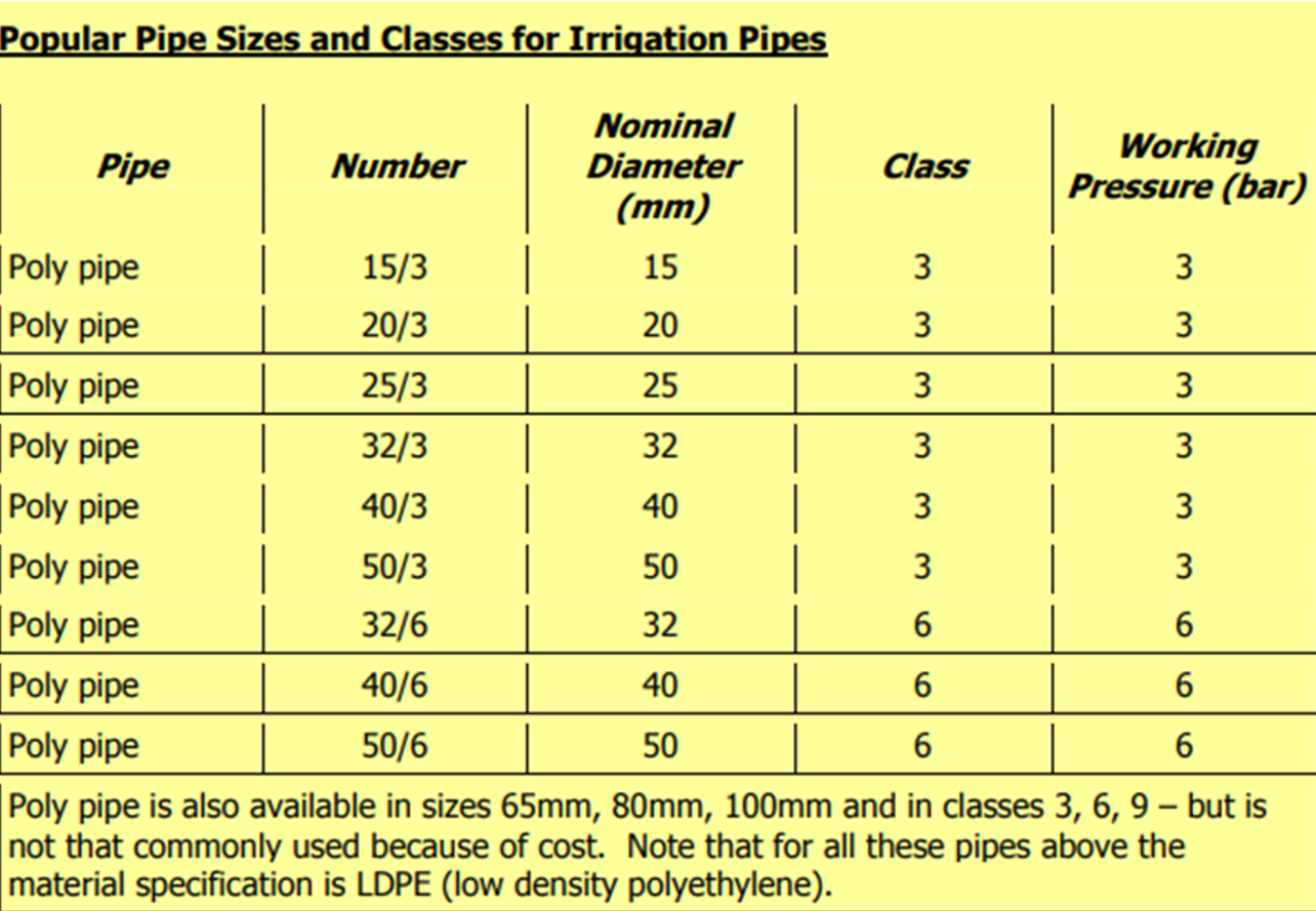
The notations next to the different sections of pipes indicate the pipe size and class for that particular section of pipe, and the length of the pipe. Using the notation of 110/6-175 for the mainline in the table above as an example, the 110/6 indicates the pipe size and class, meaning the pipe will have a nominal diameter of 110mm and will be uPVC class 6 pipes.
The second part of the notation indicates the length of the pipe in meters, meaning that this pipe will be 175m long. Note that this is the total length and includes the bends in the pipe. Pipe sections are indicated by a short line (/ or -). In the example above, the different sections of the lateral lines are marked in this way. The first lateral for block 1.3 has the numbers 25-63, 20-60 and 15-55. This means that in the first section, 25mm poly pipe is laid for 63m. In the second section, 60m of 20mm poly pipe is laid and 15mm poly pipe is laid for 55m in the third section. Classes are usually not specified for the laterals as class 3 poly pipe is used as a rule. If drippers are used, the drip line would be specified. The class of the pipe (PVC and poly pipe) indicates the pressure (in Bar) a pipe can withstand. The class notations for asbestos and cement pipes are more complicated and have to be verified with the supplier. Information on the pipe sizes and classes commonly used is as follows:


Irrigation Block Information On the irrigation design plan information with regard to each block is given in a table that shows the block number, area, spacing, emitter delivery and application rate. The area of each block is indicated in hectares (ha). In the Space column, the plant spacing is indicated. In the example the spacing is 6m x 2m, meaning that the plant rows are 6m apart and the trees are planted 2m apart in the rows. Remember that plant spacing varies according to the specific crop and variety, as well to the production area.

The plant spacing is used to calculate the number of plants per hectare, and therefore the number of emitters that are required. The plant spacing is multiplied to calculate the area per plant, and area in hectare is divided by the area per plant, which will give the plant population per hectare. Remember that 1 hectare equals 10,000m2 .

The emitter delivery in the table is used to calculate the precipitation and to check the emitters. The precipitation is used in the scheduling of the irrigation. The irrigation design plan also contains a table with the pressure and flow per block. This information is used in the irrigation scheduling.
Bill of Quantities
When a system is designed from scratch or if new blocks are designed, a bill of quantities is supplied along with the irrigation design plan. If the company that designed the system is delivering the materials as well, the bill of quantities is used to check and verify all the materials that are delivered. If the designer is not delivering the materials, the bill of quantities is used to obtain quotations for the materials and for budgeting.
