Page
Automation Control System
Completion requirements
View
Controls, instrumentation, and automation systems are key elements in the overall distribution system. The automation system is governed by the overall facility design and operational requirements.
Each individually controlled device can be linked into a main PLC, enabling coordination of the controls between various pieces of equipment.
When a is started up a start impulse is made by pressing the pushbutton positioned in the machine symbol or image on the mimic diagram. The voltage then passes via a row terminal in the control panel to another row terminal in the contactor board. From there, the voltage passes on/out to the control contact in the safety switch and from there back to the contactor board and terminal. It then passes through the control contact in the thermal relay and finally the contactor coil. The coil is energised, and the associated contacts close. The three operating contacts connect the operating circuits to the motor which starts. The retaining contact receives its voltage by way of the stop pushbutton in the control panel and connects the voltage further through the safety switch, the thermal relay and to the coil. When then the start impulse ceases, the coil receives the voltage by way of the retaining contact and remains energised and the contacts are closed. Also, the indicating contact on the contactor closes and connects the indicating voltage which comes from the control panel via terminals back to the control panel to the indicating lamp which lights up. At the same time, the coil of the so-called interlocking relay which also is located in the control panel is energised and the relay contacts which are connected into control circuits for other machines or other kinds of circuits. Close the contactor coil is connected to the neutral in the control panel via a terminal and in the contactor board. When the motor shall be stopped the stop push button is depressed at which the voltage to the maintenance contact is interrupted, the coil is de-energised, and all contacts open. If the safety switch is switched off when the contactor is energised and the motor running, the voltage to the contactor will be switched off, the contactor coil will be deenergised and all contacts will open. The same way of functioning is obtained when the overload relay trips due to motor overload, the coil will be de-energised, and the contacts will open.
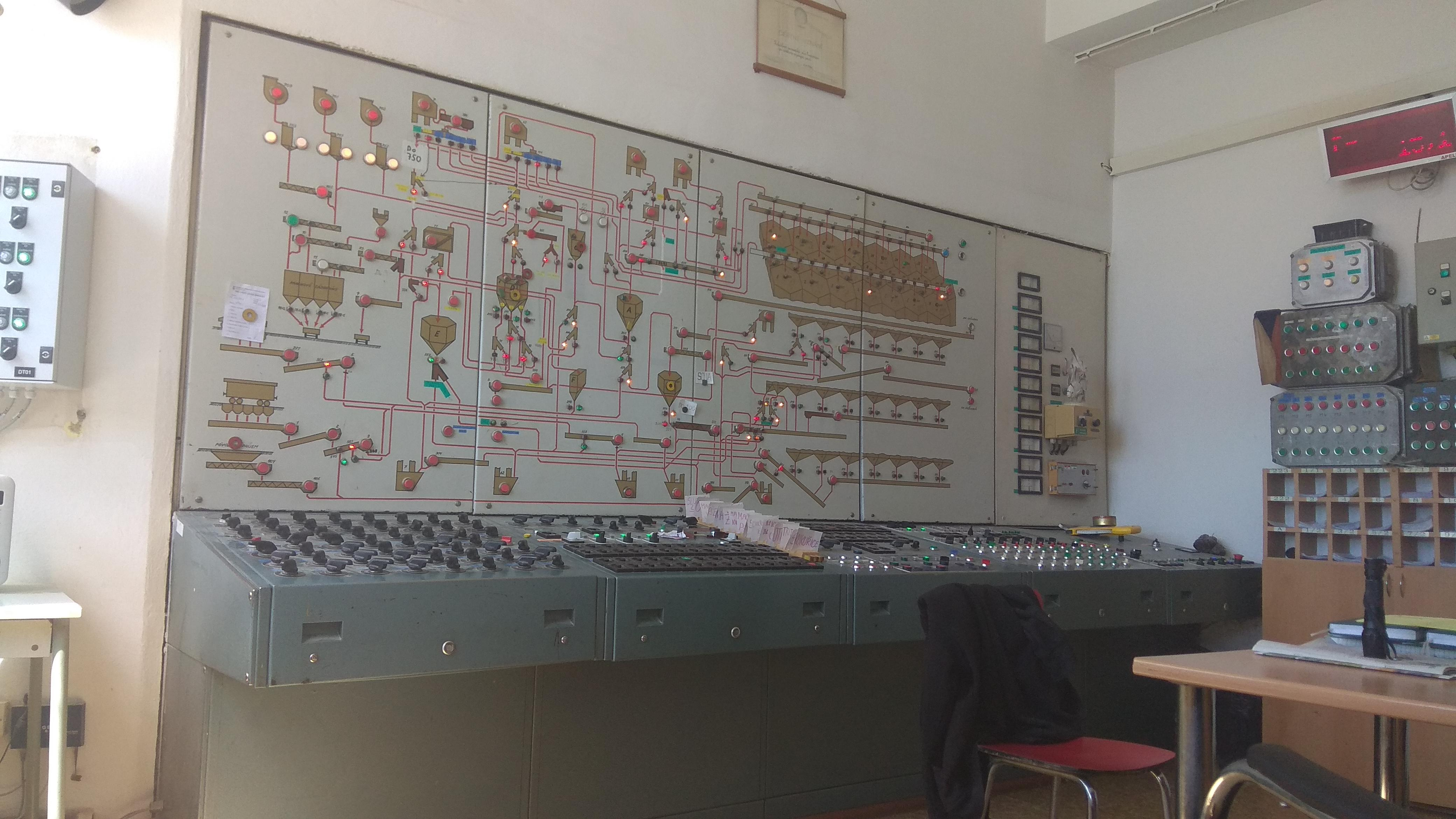
The air conditioner is provided for the purpose of safeguarding the control panel from dust as well as safeguarding the instrumentation. The control of the motors in the mechanical installation is centralised to the control panel. This signifies that the contactors are remote controlled and that the operating indication i.e. the indication of the position of the contactors is transmitted back to the control panel. The control circuits are connected to a voltage of 240V in the control panel. The indicating circuits are supplied with a voltage of 240V likewise located in control panel.
Switching the Silo On and Off
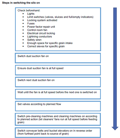
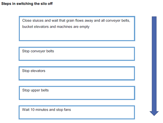
It is important to switch silo machinery on in the correct order at the correct time to ensure the efficient use of electricity. It is advised to never switch on all drivers simultaneously. It should be switched on according to the inter-circuit locking procedures of the silo. Under no circumstances should all machinery be stopped simultaneously by just switching the mimic panel off. Conveying apparatus such as pipe conveyors, chain conveyors, bucket elevators or conveyor belts must never be stopped whilst containing product.
Steps in Switching The Silo Off
Control Points When Switching The Silo On/Off
Switching on of lights: According to the Factory Act enough and correct (sparktight) lighting must be provided. The lights must be placed in such a way that lumination is provided on every work area. All the lights must be on before the silo is switched on. Tubes and electric globes must be kept clean, be replaced when defective and always have a cover.
Checking of limit switches: The purpose of these switches is to indicate the status on the control panel as well as to make the circuit locking work. Switches are fitted at each valve, sluice and dumper. These switches must be checked regularly to ensure that they are tight, as well as the lever on the arm that regulates the switch. Under no circumstances should the working of the switch be tampered with, and if unsure on how to change settings, the maintenance electrician should be contacted.
Fuses: control power failures: Fuses must be fitted to protect the electrical system against overloading and possible fire damage. If a fuse or fuse wire trips or blows, it could be repaired by replacing it with a fuse of the same size. If it should, however, after switching on or replacement, trip or blow, the maintenance electrician should be contacted.
Monitor power factor control unit: This unit is used to utilise the kVA usage optimally. The effectiveness of the whole system is thus increased, resulting in lower power usage.
Checking of control room fans: The fan is used to put the starter panels under pressure in order to keep dust out. An air filter is placed in front of the fan to clean the air. When the silo is in operation, the fan must remain switched on at all times.
Checking of electrical circuit locking: Electrical circuit locking makes it possible to operate the silo automatically and to prevent that grain is transported on routes that are not allowed and is wasted. Electrical circuit locking can eliminate the following problems:
Transportation ducts and valves are interlocked in such a way that different types of grain cannot be dumped onto the same belt or be mixed.
Buckets are interlocked to avoid that they overflow.
Condition of lightning conductors: Lighting conductors are fitted to prevent fire and damage. The conductors must be checked regularly to ensure that they are fitted and well earthed.
Working of safety sirens: Safety sirens must be switched on for at least 30 seconds before the starting of machines to check the working thereof.