Indicating Lamps
The indicating lamps are supplied with a voltage of 24V. If the indication fails to appear in an indication lamp, the light bulb is first checked by replacing it with a new working one. If this does not help there is a fault in the device which has to connect the power to the lamp – a limit switch, a relay or contactor contact – or in the wiring between these devices and the lamp holder. The cut-outs in the contacts or the limit switches can sometimes depend on there being dust on the contact surfaces, especially if the contacts have not been operated for a long time. This can, in such cases, be remedied by the operation activating the relay being carried out with the assistance from the circuit diagram. With a 24V test lamp, the circuit is checked from its beginning at the 24V phase via contacts and terminals to the spot where there is no power and where thus the fault can be found.
Push Buttons
If a function which is to follow on an impulse made in a pushbutton does not come about, the previous operations must be checked as to their correctness as well as that of the indications which have been transmitted back. If the fault is not to be found there, fault-finding has to be carried out with the aid of the circuit diagrams. With a 24V or 240V test lamp, depending on which circuits are to be checked, the voltage is tested from the beginning of the circuit via contact and terminals, first on the part of the circuit located before the make contact of the pushbutton, and then further on the part located after the contact is being tested the pushbutton must be depressed. If a relay contact that should have been closed, but is not, is found, the testing is moved on to the circuits of the coil of this relay in order to establish why this relay is not activated. The fault finding must be carried out in this manner step by step from one circuit to another until the fault is located and remedied. The fault finding has to be carried out by an experienced electrician.

Safety Switches
Safety switches are located in the proximity of the electric motor drive. Safety switches can be the cause of unmotivated and difficult to explain stops of the operating, quite simply because they, involuntarily or as a joke, can be switched off a short moment and then be switched on again. It is, however, not permitted to block or lock them as it always must be possible to switch them off should anything happen
Level Indicators
Level indicators are installed in buffer bins, hopper bins, storage bins, and in chain conveyors. The level indicator stops the conveyor if the end outlet is so full of grain that the indicator is actuated. The end outlet must then be cleared before the conveyor can be started up again. At times it can happen that a conveyor begins to create unusually much overflow and subsequent interruptions of the operating. The reason for this can either be that a brush on the chain is out of order or that a gate is so incorrectly adjusted that it does not open completely. The reason shall be established, and the fault remedied.
Limit Switches
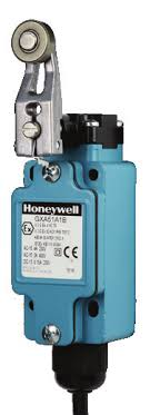
The adjustment of the points of actuation of the limit switch shall be carried out with good precision so that gates and valves really are in the right positions when the indicating lamps on the control panel are lit. If the adjustment is incorrect, some grain can fall down into another conveying chain or into another bin. If the setting of the positions of gates and valves is done carelessly and with great force, a previously correct adjustment can be altered or another fault can be caused on the setting with incorrect conveying as the result. Since these faults can be difficult to discover, it is important that the manual operation is done with care and that occasional inspections also are made in the inspection hatches where there is not supposed to come any material.

Labour Factor Unit
Inspect and test unit at least two times per shift (bucket elevators are started one-by-one without load). If the unit does not start, the maintenance electrician must be informed. Clean the panel with a dry cloth. The unit should be serviced by a qualified person on a monthly basis.
Low Speed Relays
The function of the low speed relay is to monitor that the elevator belt is operating at the right speed. If the speed is too low, the low speed relay will automatically switch off the motor power and the elevator stops altogether. If the belt runs too slow, this may be due to slippage on the upper driving shaft. This sometimes results in the belt becoming overheated, and a fire can be caused. The belt must then be stretched. If the elevator is started with grain in the buckets and the down pipe to the elevator, the belt can be completely locked. The elevator boot must then be cleared from grain before starting is tried again. It is very important that the start impulse is not made longer than about 2 seconds. This is because the low speed relay is bridged during the starting up sequence and thus cannot protect the belt.
Click here to view a video that explains how to keep the silo clean.